|
P dV's Custom Process Control Systems Capabilities Select from the list below:
|
| • Introduction to P dV's Control Systems |
| • Engine Test Cell Control Systems |
| • Custom Process Control Systems |
|
• Instrumentation & Process Control Hardware
|
|
|
|
P dV Identifies The Need for Engine Test Cell Control Systems
|
|
P dV's first complete data acquisition system, including hardware and software integrated together, was designed in 1995, and was born out of necessity.
The existing test cell data acquisition system was simple and rigid, and did not provide for the test-to-test flexibility the client required.
Using National Instruments hardware with growth potential, and LabVIEW software for fast code changes, a new data acquisition system was designed to provide
the ability to adapt to the client's rapidly changing requirements. While observing test cell operators conducting tests, it became apparent that, in the
best interest of the client in terms of repeatable test results and the ability to conduct testing faster, test cell control would be required.
By using existing analog and digital outputs, and the existing LabVIEW software, a test cell control program was designed and integrated with the data
acquisition program. This greatly improved repeatability in the data acquisition process, and significantly reduced test cell operator workload. Beginning
with engine speed and dynamometer load control, other features were added as the advantages of control capabilities became apparent.
|

|
• Integrated Data Acquisition Systems with Calibration, Information Management and Test Control
Over the years of data acquisition system development, a philosophy emerged that has formed the basis of P dV's data acquisition and control systems. Acquiring and recording data is not enough. Specific engine and test information must be captured and managed. Instrumentation must be calibrated. Post-processing of important parameters from acquired data is now acomplished in real time. Test control parameters must to be accurate and repeatable, and reduce the chance of operator error. The test operator must be comfortable with the system setup and usage. Above all, the system must be capable enough to meet all client and test requirements, and flexible enough to meet changing test needs. (for additional information on specific data acquisition systems, see Custom Data Acquisition System Applications)
|
|
|
|
|
|
P dV Designs, Develops, and Implements Engine Test Cell Control Systems
|
|
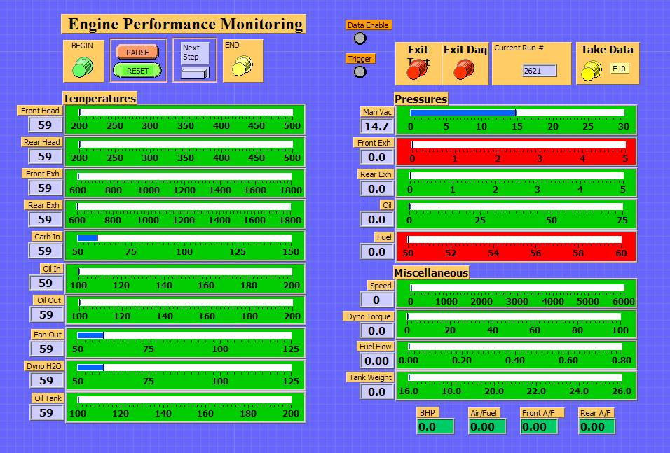
• Custom Engine Test Cell Data Acquisition & Control Systems
Prompted by the need for accurate and repeatable test conditions, and defined by customer requirements, test control systems are designed and integrated
to complement the data acquisition system in an engine test cell. P dV's control system designs have included the following features:
|
|
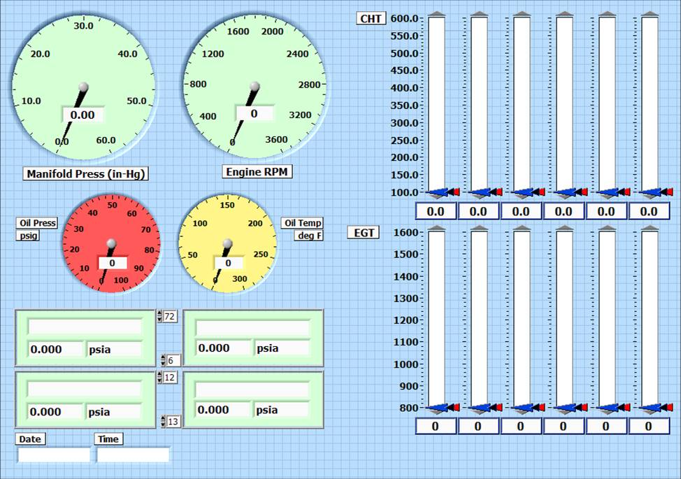
• Automatic Test Cycle Control
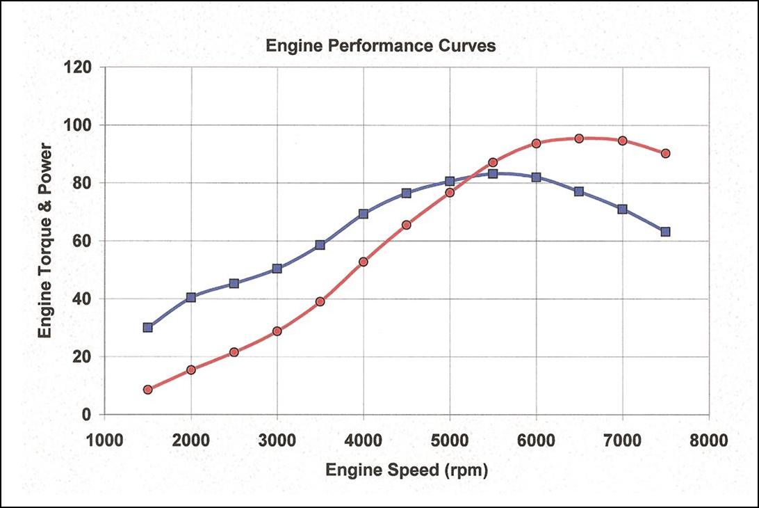
One example of test control applied to performance development is where an air-cooled engine was placed under test using cylinder head temperatures to trigger the events in a test cycle. After the engine was fully warmed up, it was allowed to idle with cooling fans on to allow the cylinder head to cool down below a preset temperature. Then, the engine was ramped to a given speed and load (controlling throttle and dyno speed), and held there while the cylinder head was allowed to heat up to a target temperature, at which time a data point was taken. Upon taking the data point, the engine was returned to idle to cool the cylinder head. This cycle was repeated, where each successive speed and load was altered until a pre-determined speed/load map was achieved, giving a performance map with data taken automatically at consistent cylinder head temperatures.
|

|
• Autonomous Test Monitoring and Control
Another example of test control was applied to an engine durability test where a speed and load matrix versus time was repeated in successive cycles until a
specified number of cycles (& therefore hours) was completed. Features of the durability cycle included:
|
|
When conditions called for autonomous testing with minimal operator monitoring (one operator monitoring 4 test cells), the test cell control system was
adapted to monitor each data acquisition channel relative to specified levels. These levels were divided into two categories: alerts and alarms, with high
and low trigger levels for each. If measured values triggered the low or high alert or alarms, the control system would take appropriate action. These
actions ranged from notifying the operator with panel displays, to shutting down the engine, as required.
|
|
|
|
|
|
P dV Provides Custom Process Control System Design & Development
|
|
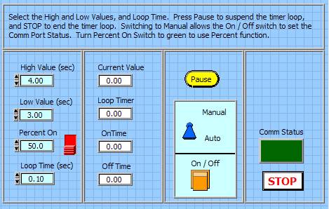
• Simple: Solenoid Control Program
P dV has experience in setting up control systems from simple to complex. One simple system consisted of controlling two solenoid valves, turning them on and off with an adjustable cycle time (period), and also percentage of "on" time (duty cycle). In addition, a random number generator was used to randomize the time between turning the solenoids on. A manual override was included, allowing the user to manually cycle the solenoids to test them. The control signals were sent to a set of solid state relays through the serial port, minimizing the control hardware requirements. The solid state relays would allow the 5 volt TTL signal to switch higher AC or DC voltages to drive the solenoids.
|
|
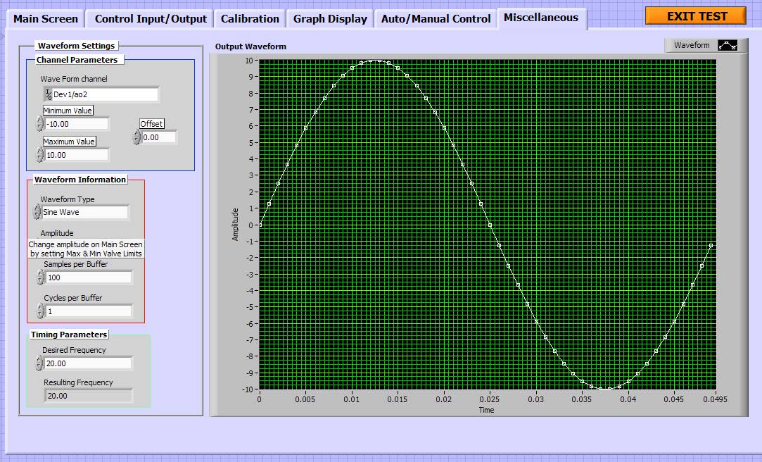
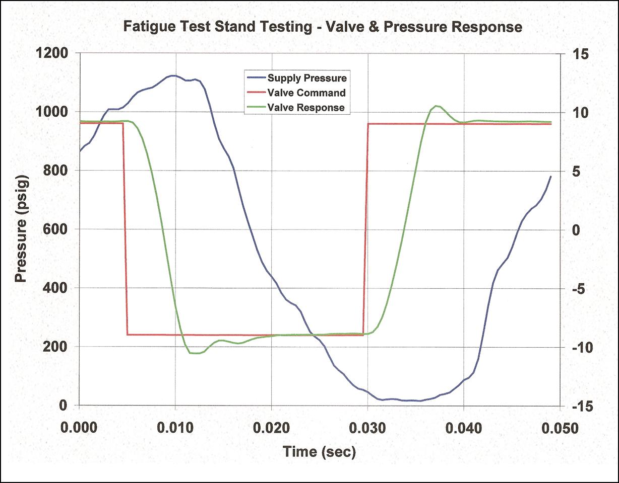
• Complex: Hydraulic Pressure Test Stand Program
A much more complex data acquisition and control system, designed and integrated by P dV, involved controlling a hydraulic pressure fatigue test stand. This stand used a hydraulic pump and control valve to cycle pressure to a test article, thereby fatiguing it. A separate motor controller drove the electric motor and hydraulic pump combination, providing hydraulic pressure to a setpoint passed to the controller by the software. The hydraulic oil was heated as it passed through the test article, and was cooled upon return to a reservoir. A data acquisition and control system was designed and integrated with the following features:
|
|
• inputs for supply pressure and test time or number of cycles
• user-selected pressure cycle frequency and valve excursion limits • user-selected valve/pressure waveform: sine, square, sawtooth • drive the control valve using selected waveform • closed-loop control of oil pressure by a setpoint passed to the motor controller • control of oil temperature, and monitoring of cooling water temperature • start of test cycle when conditions are met • alert and alarm functions for unattended testing • input trigger levels for temperature and pressure limits • display of which parameter tripped preset alert/alarm levels • stop or pause the test when certain alert/alarms are tripped • sample and store data at predetermined data rate, including test time and number of cycles
|
|
|
|
|
|
P dV Provides Process Control Hardware & Instrumentation Support
|
|
• Hardware and Instrumentation: design and specification
P dV's experience in designing, constructing, and instrumenting not only component test stands, but also the data acquisition and control systems used to run them, can be used to help you with your application. P dV can specify the required hardware for the test stand, and the instrumentation to meet the data acquistion and control requirements.
|
|
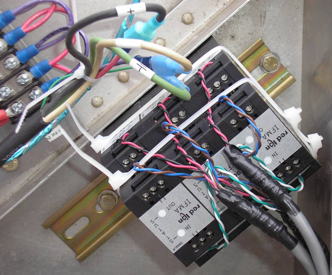
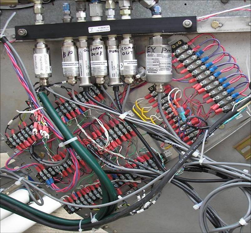
• Hardware and Instrumentation: installation
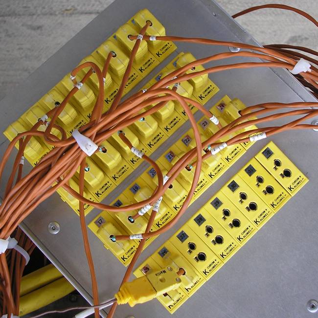
Having set up numerous test cells and component test stands, P dV can help install the instrumentation required for your application. P dV has experience setting up pressure transducers, thermocouples, magnetic pickups, hall effect sensors, frequency-to-voltage converters, linear and rotary position transducers, voltage dividers, laminar flow element meters, turbine flow meters, acoustic and coriolis flow meters, and load cells. P dV is available to specify and supervise the installation and commissioning of instrumentation setups as required. This includes best practices with regards to wiring of transducers and sensors, power supply requirements for instrumentation, and shielding and grounding requirements.
|
|
• Instrumentation Calibration Support
P dV has experience with the calibration requirements of many different types of instruments including temperature, pressure, flow rate, force, rotation speed, and others. P dV can set up the data acquisition software to work with the data acquisition hardware to read and record the output of the sensor or transducer being calibrated. P dV has calibrated and maintained records for sensors as required to meet ISO standards for documentation.
|
|
|
|
|